Lab 3: Keypad Scanner
Introduction
In this lab I designed and verified a 4×4 matrix keypad scanner on an iCE40 FPGA. The design registers each key exactly once (on press), filters bounce, ignores additional keys while one is held, and displays the last two hex digits on a dual common-anode seven-segment display (most recent on the right). The keypad orientation is aligned with the display.
Display polarity. Common-anode → Seg[6:0] are active-LOW and digit enables select which anode is active.
System Overview
Block Diagram
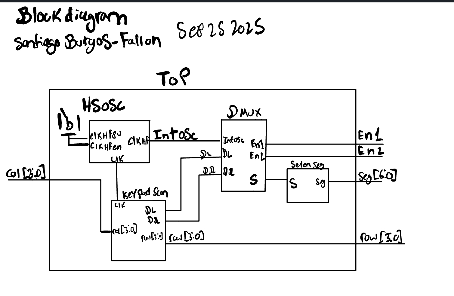
Top-Level Architecture
Clocking: Lattice
HSOSCat ~6 MHz (CLKHF_DIV=2'b11).Keypad interface:
- Rows (
Row[3:0]) are FPGA outputs, one row driven LOW at a time (scan). - Columns (
Col[3:0]) are FPGA inputs with pull-ups (PULLMODE=UP). A pressed key shorts the active low row to its column → that column reads0.
- Rows (
Scanner (
KeypadScan):Round-robin row scan (≈2 kHz), 2-FF synchronizers on
Col[3:0].FSM with states IDLE → DEB → HELD.
- On first detection, freeze the candidate row/col and debounce for a few scan ticks.
- Emit a 1-cycle
key_validon acceptance, then ignore other keys until all columns return high.
Display path: On
key_valid, shift{D_left, D_right} ← {D_right, key_code}. A singleSevenSeginstance decodes the selected nibble;DMuxalternates enables (En1,En2) and feeds the decoder input (s) at a fixed duty to avoid brightness variation.

State Machine Specification
State Diagram

State Transition Table
IDLE – transitions
| Current State | Condition (plain English) | Next State | Notes |
|---|---|---|---|
| IDLE | A key seems pressed (while scanning, some column reads LOW) | DEB | Latch the candidate key = (active row, first LOW column); compute hex |
| IDLE | Otherwise | IDLE | Continue round-robin row scan |
DEB – transitions
| Current State | Condition (plain English) | Next State | Notes |
|---|---|---|---|
| DEB | All columns are HIGH again (looks like release or a glitch) | IDLE | Abort debounce; resume scanning |
| DEB | On the scan strobe, the same candidate column is still LOW and the stable count just reached the target (e.g., 3 in a row) | HELD | Accept the key; emit a one-clock key_valid pulse |
| DEB | On the scan strobe, the same candidate column is still LOW but the stable count hasn’t reached the target | DEB | Keep counting consecutive stable observations |
| DEB | On the scan strobe, the candidate column is not LOW | DEB | Reset the stable counter to zero |
| DEB | Otherwise | DEB | Keep the candidate row held LOW and wait for next scan strobe |
HELD – transitions
| Current State | Condition (plain English) | Next State | Notes |
|---|---|---|---|
| HELD | All columns are HIGH (the key has been fully released) | IDLE | Return to scanning; allow a new key |
| HELD | Otherwise (key still held, or other keys also pressed) | HELD | Ignore additional keys until full release |
Outputs & Actions (per state)
| State | Row Drive (what we drive on the keypad) | Registers / Counters (what we latch/update) | One-Cycle Outputs |
|---|---|---|---|
| IDLE | Round-robin: one row LOW at a time (…1110 → 1101 → 1011 → 0111…) |
On first LOW column: latch candidate row & column, compute and hold candidate hex, clear stable counter | key_valid = 0 |
| DEB | Freeze: keep only the candidate row LOW | On each scan strobe: if same column still LOW → increment stable counter; else reset to 0 | When target count reached on a strobe: key_valid = 1 (one clock) |
| HELD | Freeze: keep only the candidate row LOW | Wait until all columns HIGH (full release); counters unchanged | key_valid = 0 |
Mini-glossary (for the table)
- Scan strobe: periodic tick that advances row scan and paces debouncing.
- Candidate key: first detected (row, column) pair; row is held during debounce.
- Stable count: number of consecutive scan strobes where that same column remains LOW (target e.g. 3).
- All columns HIGH: no key asserted (
1111due to pull-ups).
One-liners for implementation cross-check
- Accept press when:
state==DEB && scan_tick && stable_cand && deb_cnt==N_stable-1→key_valid<=1,state<=HELD. - Abort bounce when:
state==DEB && all_released→deb_cnt<=0,state<=IDLE. - Ignore additional keys while HELD: do nothing until
all_released.
Debouncing & Metastability
- Synchronizers: Each
Col[x]passes through a two-flip-flop chain (col_s1 → col_sync) clocked at 6 MHz to mitigate metastability. - Debounce window: Acceptance requires three stable observations of the candidate column under a frozen row. This balances responsiveness and immunity to mechanical bounce.
- Single-event guarantee:
key_validis generated once, on the press edge only. While in HELD, new presses are ignored until release.
Timing & Multiplexing
Scan Timing
A 13-bit divider creates a ~2 kHz scan tick. Rows step: 1110 → 1101 → 1011 → 0111. The debounce counter advances only on scan ticks. Timing can be seen on top Module Wave form.
Display Timing (DMux)
DMux toggles a digit select at ~50 Hz (counter=60 000 at 6 MHz → 50 Hz).
s = (DivClk) ? D_right : D_leftEn2 = DivClk,En1 = ~DivClk- Constant duty keeps brightness uniform, independent of the number of lit segments.
Timing can be seen on top Module Wave form.
Pinout & Orientation
- Rows (outputs): connect to keypad R0..R3.
- Columns (inputs w/ pull-up): connect to keypad C0..C3.
- The map_hex table encodes the keypad legend for
(row, col)indices consistent with the chosen orientation.

HDL Summary (files & roles)
top.sv— HSOSC,KeypadScan, capture registers for last two digits,DMux,SevenSeg.KeypadScan.sv— row scan, 2-FF input sync, IDLE/DEB/HELD FSM,map_hex(r,c).DMux.sv— display multiplexer + digit enables (fixed duty).SevenSeg.sv— combinational hex→segments (active-LOW).
All combinational logic is in always_comb; sequential is in always_ff with a single driver per reg (no latches, no tri-states).
Simulation & Verification
Testbench Strategy
A behavioral keypad model drives
Col[3:0]LOW only when the DUT selects the matching row LOW.The TB issues a sequence of 16 keys (walks the matrix), waits for
key_valid, and then checks the two displayed digits by sampling when each enable is active.Negative tests:
- Hold one key, “press” another → verify the second is ignored until release.
- Inject brief bounces on a column line → ensure single registration.


Results (simulation)
- Each programmed key press produced one
key_validpulse and the expectedkey_code. - With one key held, additional simulated presses did not register.
- Display sampling showed stable, non-flickering output; both digits had equal duty.
Hardware Bring-Up & Measurements
- Verified with a multimeter that each button shorts exactly one Row to one Col (<100 Ω) and that
Colidles at1111with no key (internal pull-ups). - Confirmed row order and column order match the
map_hexorientation by observing a temporary LED debug (~Row,~Col) and adjusting constraints where needed. - Final board test: pressing any key updates the right digit; the previous right digit shifts to the left. Press-and-hold does not cause repeats; additional presses are ignored until release.
Design Tradeoffs & Alternatives
- Debounce length: I chose 3 scan-ticks (≈1.5 ms at ~2 kHz) for a good balance of responsiveness vs. bounce immunity. Longer windows reduce false triggers but feel less snappy.
- Scan rate: ~2 kHz row stepping comfortably exceeds bounce dynamics and avoids aliasing; slower scanning risks missing very short taps.
- Single decoder + mux: Minimizes area and guarantees identical glyphs; the tradeoff is a need for careful duty control to keep brightness uniform.
- First-press policy vs. NKRO: For a diode-less matrix, “first-press wins” avoids ghosting; true multi-key (NKRO) would require per-switch diodes or a more complex detection + ghost-masking strategy.
- Synchronizers: 2-FF is sufficient at 6 MHz; 3-FF would further reduce MTBF at the cost of extra latency.
Schematic Notes
- Columns: inputs with PULLMODE=UP
- Rows: push-pull outputs; one driven LOW at a time.
- Display: common-anode; segment resistors per segment; enables at constant duty.
Conclusions
The implemented keypad scanner meets the lab requirements:
- Correctly reads the 4×4 keypad, debounces, and registers once per press.
- Ignores additional keys while one is held.
- Drives the dual 7-segment display with stable brightness and correct ordering (most-recent on right).
- Uses clean, latch-free, tri-state-free RTL with proper synchronizers.
Time spent: (12 hours). Known limitations / future work:
- Add a compile-time option to speed the scan/dividers in simulation.
- Auto-detect row/col orientation at power-up to reduce pin-map bring-up friction.
Appendix
File List
top.sv
KeypadScan.sv
DMux.sv
SevenSeg.sv
hsosc_sim.sv   // simulation model only
*_tb.sv        // keypad + display testbenches
Key Equations
- Display scan: \(f_{\text{scan}} = \dfrac{f_{\text{clk}}}{2N}\) (N =
DMuxterminal count). - Debounce window: \(T_{\text{deb}} = N_{\text{stable}} / f_{\text{row-scan}}\).
AI Implementation
Prompt used
Target device: Lattice iCE40 UP5K FPGA with internal high-speed oscillator (~20 MHz).
Write synthesizable SystemVerilog to scan a 4×4 matrix keypad and display the last two hex keys pressed on a dual 7-segment display. Implement: • A clock divider that derives a scan clock on the order of 100–200 Hz from the internal oscillator. • A keypad scanning controller that iterates one active-low column at a time and samples active-low rows, registering at most one key per press (debounce-by-design), ignoring additional presses while any key is held, and allowing a new registration only after release. • A top level that updates two hex digits (older and most recent) when a new key is registered and drives a time-multiplexed two-digit 7-segment display without visible flicker and with balanced brightness. Use idiomatic SystemVerilog (e.g.,
logic,always_ff, enumerated states for FSMs). Provide clean module boundaries and keep all state synchronous. Include brief comments explaining the design choices. Create a new Radiant project, type the code generated by the LLM in and analyze the results. If the synthesis fails, type the error message back into the LLM to see what suggestions it generates.
What the LLM produced
Good ideas it used
- Clear module split:
KeypadScan(scanner + debounce FSM),DMux(digit scan/mux),SevenSeg(combinational hex→segments),top(capture two digits, wire-up). - Synchronous FSM with three states (IDLE → DEB → HELD), a one-shot
key_validpulse on accept, and two-flip-flop synchronizers on the asynchronous column inputs. - Round-robin row drive and frozen row during debounce, which prevents ghosting and enforces “first press wins.”
- Time-multiplexed display with fixed duty for uniform brightness, and active-LOW segment patterns for a common-anode display.
- Included a scan tick to pace debounce (stable-N policy), keeping all counters/sequencing in
always_ffand decoding inalways_comb.
- Clear module split:
Gaps I had to fix
- Row/column polarity & direction: the prompt assumed active-low columns and sampled rows, but our board drives rows (active-LOW) and reads columns (with pull-ups). I corrected the interface and comments to match hardware.
- Key mapping: the default
(row,col)→hexmap didn’t match the physical keypad legend; I rewrotemap_hexto our layout. - Multiple drivers risk:
key_validwas assigned in more than one procedural context in one draft. I consolidated to a singlealways_ff. - Debounce edge case: the counter was clocked every system cycle; I tied it to the scan strobe so stability is measured per row sample.
- Simulation speed: initial dividers made sims painfully long; I added small counts under a guarded sim mode while leaving hardware rates intact.
Quality rating (and why)
- Rating: A-
- Why: The LLM delivered a solid modular architecture and a correct synchronous FSM with proper input synchronization and single-event registration. Most fixes were integration details (board polarity, key legend, divider sizing) rather than structural rewrites.
Did it synthesize first time?
Almost. It compiled after minor edits:
- Align row/column direction and polarity with our board.
- Fix a single-writer rule on
key_valid. - Adjust the
(row,col)→hexlookup to the actual keypad legend. - Tweak divider constants (fast for sim, slow for hardware) and confirm no latches/tri-states.
What I’d do differently next time with an LLM
- State the physical contract explicitly in the prompt: “Rows = outputs, active-LOW; Columns = inputs with pull-ups (idle=1111); Segments active-LOW; digit enables En1/En2 select left/right.”
- Provide the keypad legend and pin swap up front and ask the model to generate
map_hexfrom a small (row,col)→label table. - Ask for
+ifdef SIMdividers from the start to keep waveforms short and readable. - Require one-process-per-reg and “no
$clog2/parameters” if a strict style is desired, so the draft matches house style without edits.